Ultrasonic Testing (UT)
Ultrasonic inspection techniques are commonly divided into three primary classifications.
1) Pulse-echo and Through Transmission. (Relates to whether reflected or transmitted energy is used)
2) Normal Beam and Angle Beam (Relates to the angle that the sound energy enters the test article)
3) Contact and Immersion (Relates to the method of coupling the transducer to the test article)
1 Test Techniques - Pulse-Echo
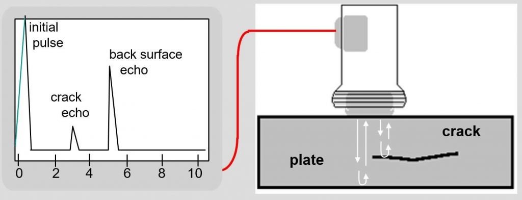
In pulse-echo testing, a transducer sends out a pulse of energy and the same or a second transducer listens for reflected energy (an echo).
Reflections occur due to the presence of discontinuities and the surfaces of the test article.
The amount of reflected sound energy is displayed versus time, which provides the inspector information about the size and the location of features that reflect the sound.
Digital display showing signal generated from sound reflecting off back surface.
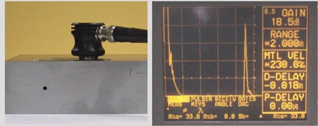

Digital display showing the presence of a reflector midway through material, with lower amplitude back surface reflector.
The pulse-echo technique allows testing when access to only one side of the material is possible, and it allows the location of reflectors to be precisely determined.
Test Techniques – Through-Transmission
Two transducers located on opposing sides of the test specimen are used. One transducer acts as a transmitter, the other as a receiver.
Discontinuities in the sound path will result in a partial or total loss of sound being transmitted and be indicated by a decrease in the received signal amplitude.
Through transmission is useful in detecting discontinuities that are not good reflectors, and when signal strength is weak. It does not provide depth information.

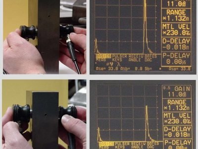
Digital display showing received sound through material thickness.
Digital display showing loss of received signal due to presence of a discontinuity in the sound field.
2 Test Techniques – Normal and Angle Beam

In normal beam testing, the sound beam is introduced into the test article at 90 degrees to the surface.
In angle beam testing, the sound beam is introduced into the test article at some angle other than 90.
The choice between normal and angle beam inspection usually depends on two considerations:
The orientation of the feature of interest – the sound should be directed to produce the largest reflection from the feature.
Obstructions on the surface of the part that must be worked around.
3 Test Techniques – Contact Vs Immersion
Inspection Applications
- Flaw detection (Lamination, cracks, inclusions, porosity, )
- Erosion & corrosion thickness gauging
- Assessment of bond integrity in adhesively joined and brazed components
- Estimation of void content in composites and plastics Measurement of case hardening depth in steels
- Estimation of grain size in metals
Advantage of Ultrasonic Testing
- Sensitive to small discontinuities both surface and
- Depth of penetration for flaw detection or measurement is superior to other
- Only single-sided access is needed when pulse-echo technique is
- High accuracy in determining reflector position and estimating size and
- Minimal part preparation
- Electronic equipment provides instantaneous
- Detailed images can be produced with automated
- Has other uses such as thickness measurements, in addition to flaw
Limitations of Ultrasonic Testing
- Surface must be accessible to transmit
- Skill and training is more extensive than with some other
- Normally requires a coupling medium to promote transfer of sound energy into test
- Materials that are rough, irregular in shape, very small, exceptionally thin or not homogeneous are difficult to
- Cast iron and other coarse grained materials are difficult to inspect due to low sound transmission and high signal
- Linear defects oriented parallel to the sound beam may go
- Reference standards are required for both equipment calibration, and characterization of flaws.

